Built work · Mechanical design lead
Warman Design & Build
The brief
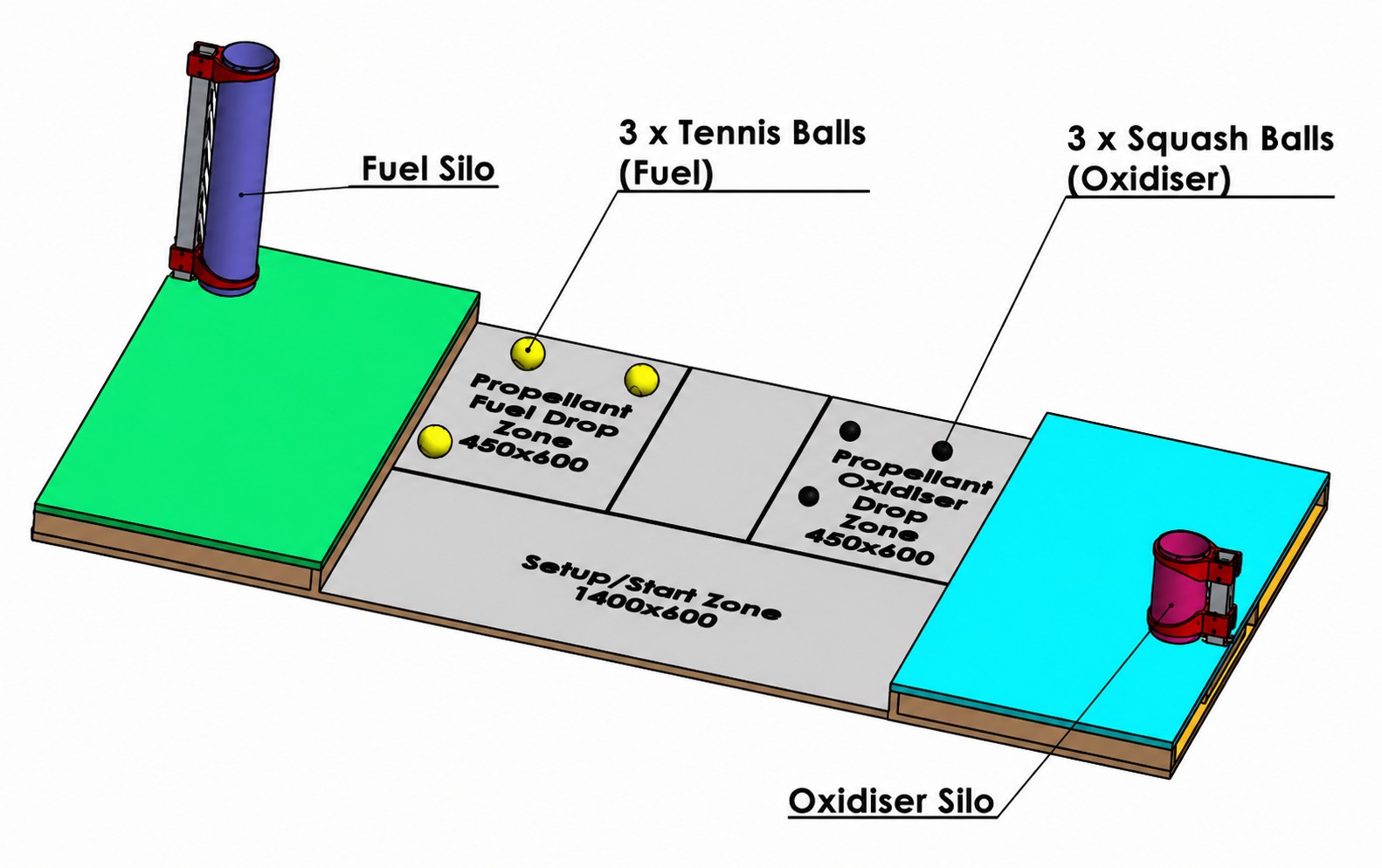
Design, build, and demonstrate a scale prototype of an autonomous system for handling hazardous materials, constrained to a 400 mm build volume. It had to collect propellant and oxidiser vessels from separate drop zones and deposit each in its matching silo, as quickly as possible.
Software Autodesk Fusion 360 · Materials PETG, plywood, MDF, steel · Role Mechanical design leadWhat I did
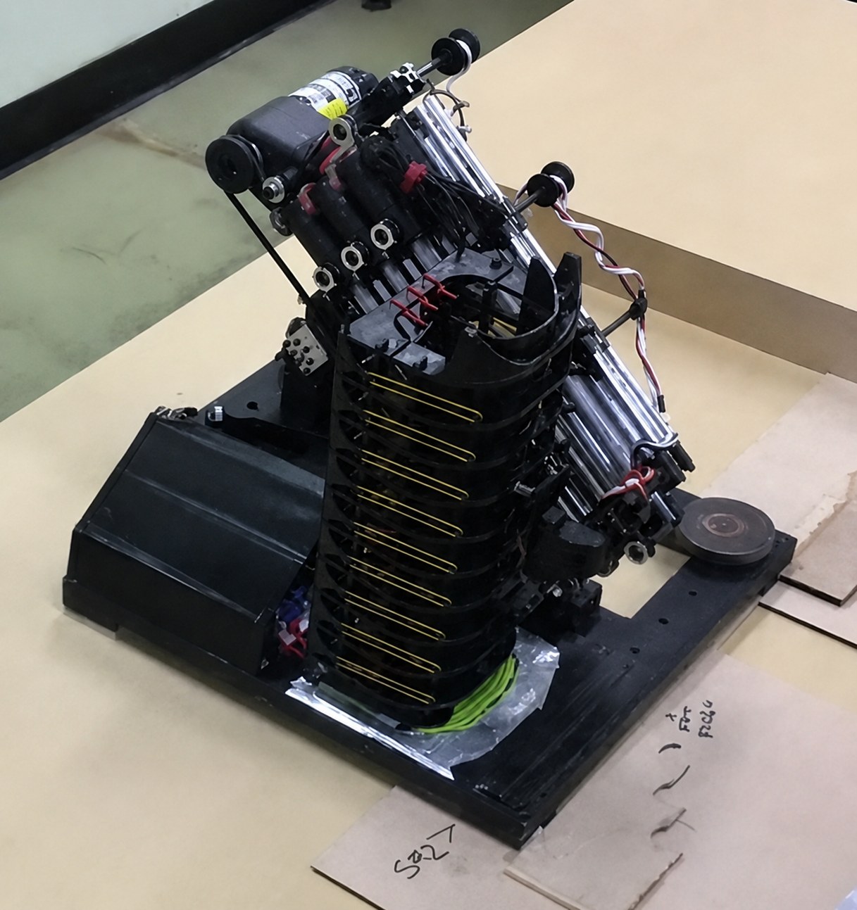
Took ownership of detailed mechanical design and fabrication, converting the team’s initial concept into a static cascading crane with passive vessel handling.
Modelled every mechanical component and assembly in Fusion 360, resolving interfaces and fits.
3D-printed the non-standard PETG parts, machined the rails and assembled the machine.
Tested the mechanical subsystem, assisted with electrical testing and then tested the integrated machine.
The decisions that mattered
A 1.33 mm window
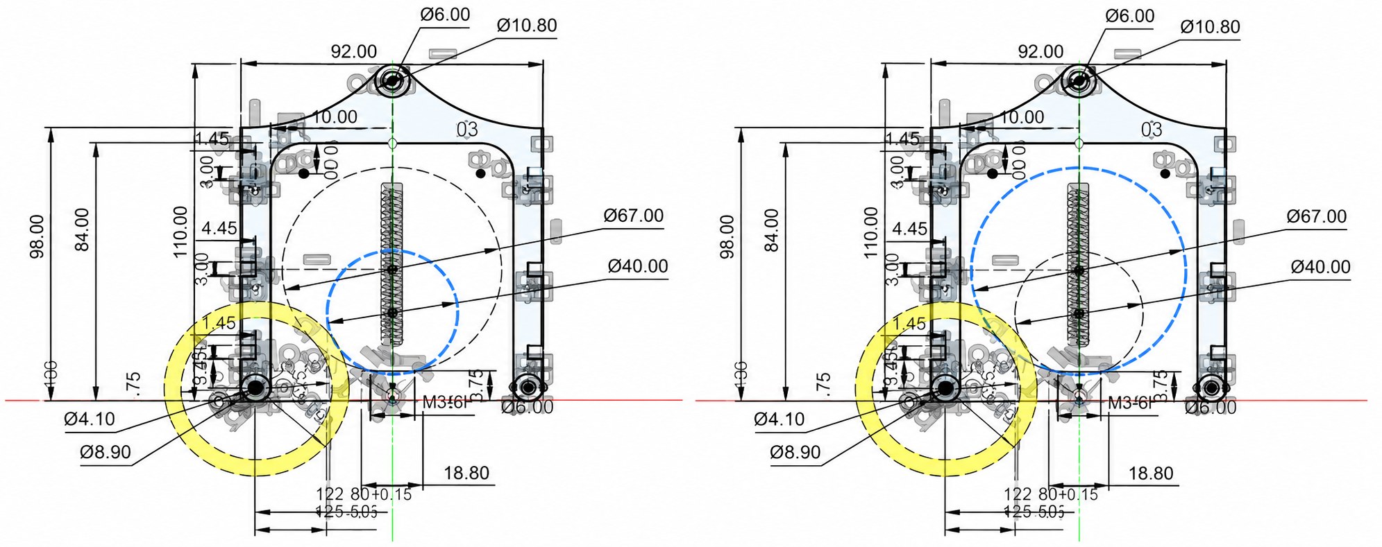
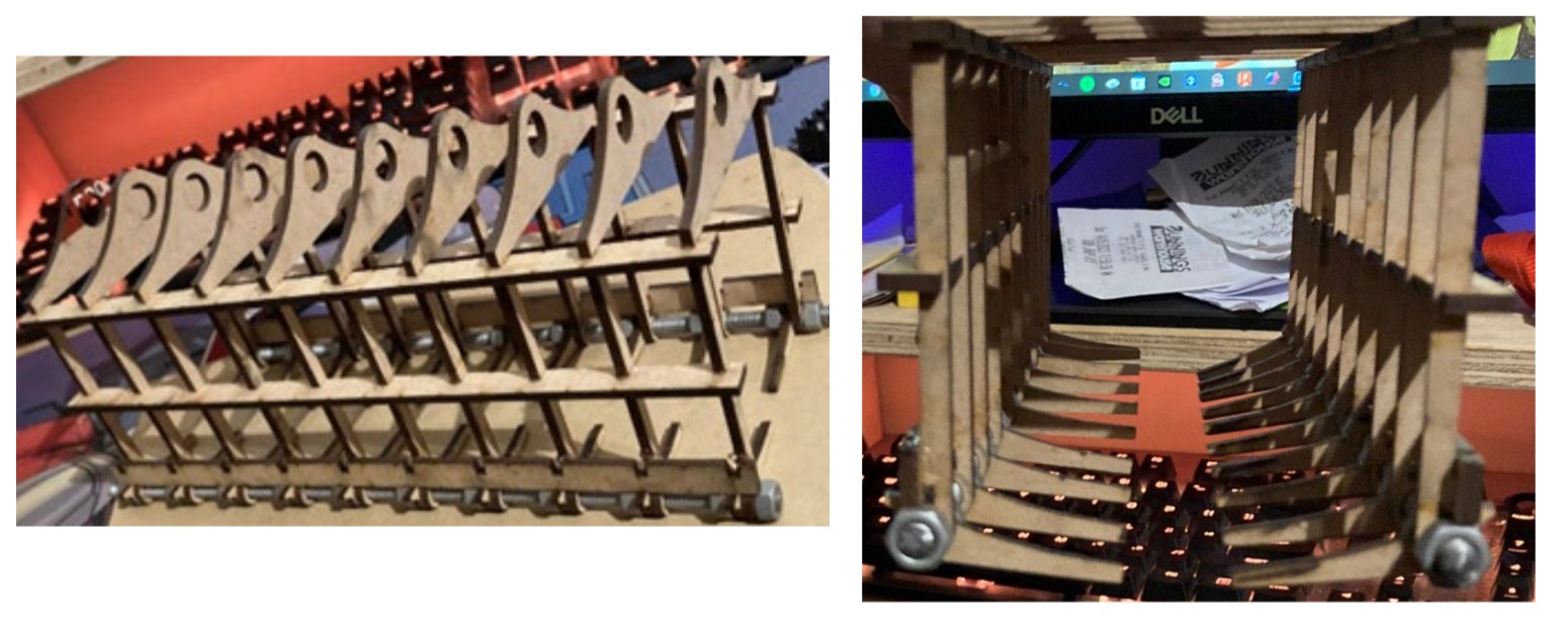
One passive toolhead had to lift two ball sizes: 67 mm and 40 mm. The combs ride up over a ball and drop closed behind it.
That only works inside a 1.33 mm band of comb-tip length. Longer fouls the tennis ball going in; shorter and the squash ball drops straight back out. The first toolhead was laser-cut and iterated by eye, and worked poorly.
When I took over design & fabrication:
I calculated the correct comb length, and achieved a working geometry in one 3D-printed iteration.
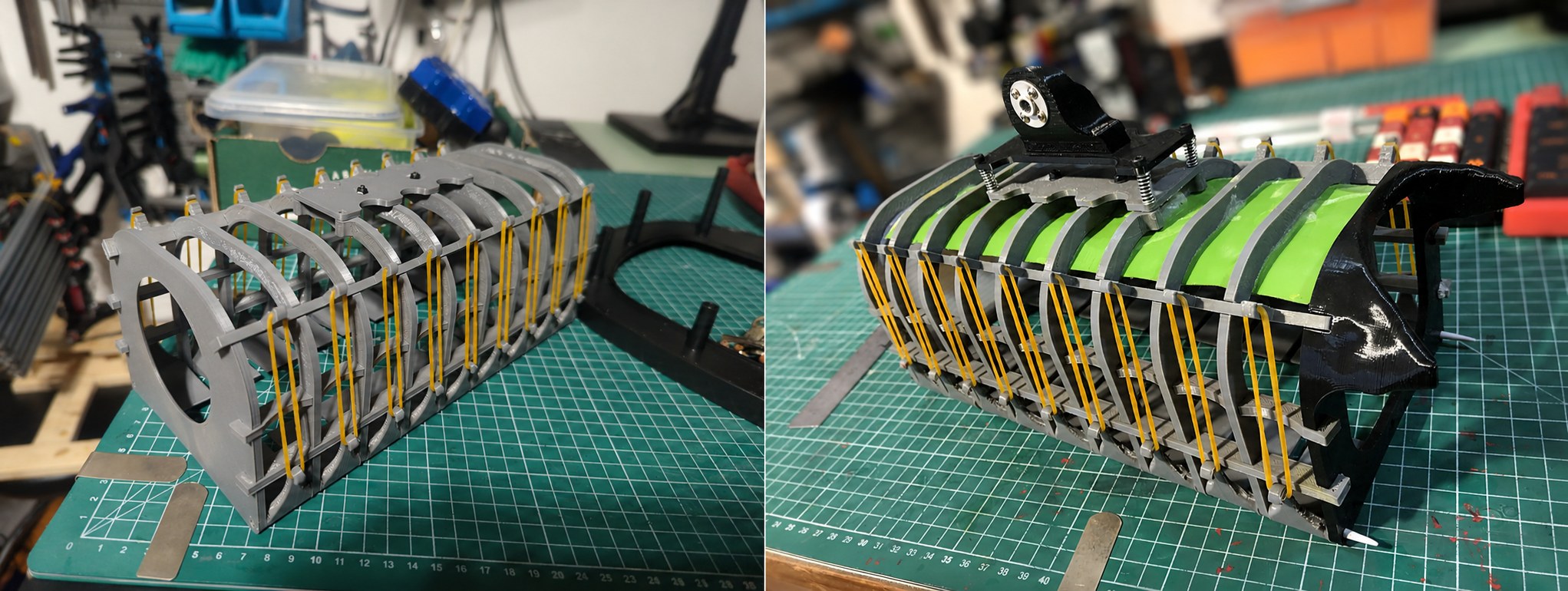
Changed to a rubber-band-loaded comb because the previous passive combs were binding.
Redesigning the toolhead in PETG with hollow infill halved its mass.
Stiffness against mass
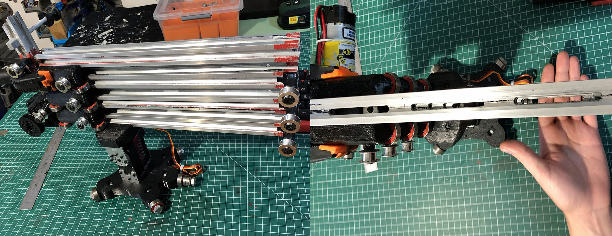
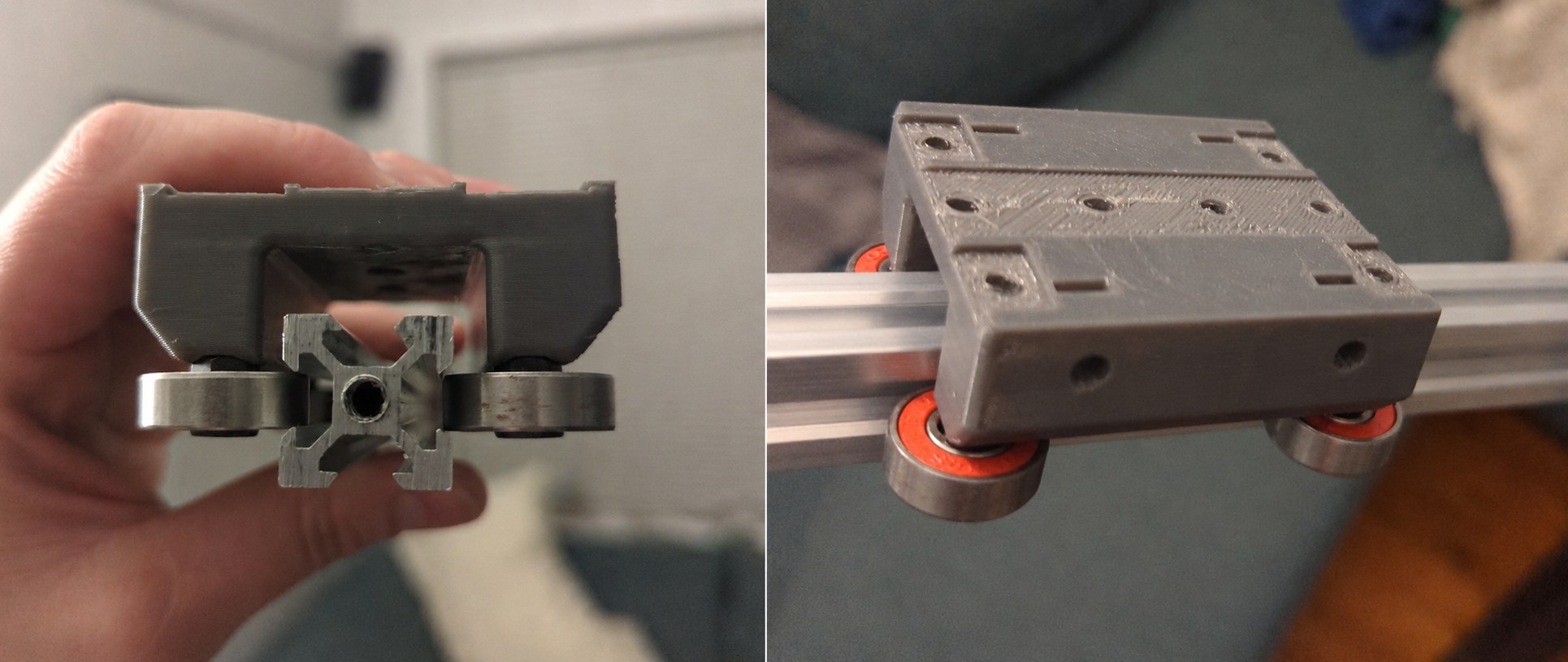
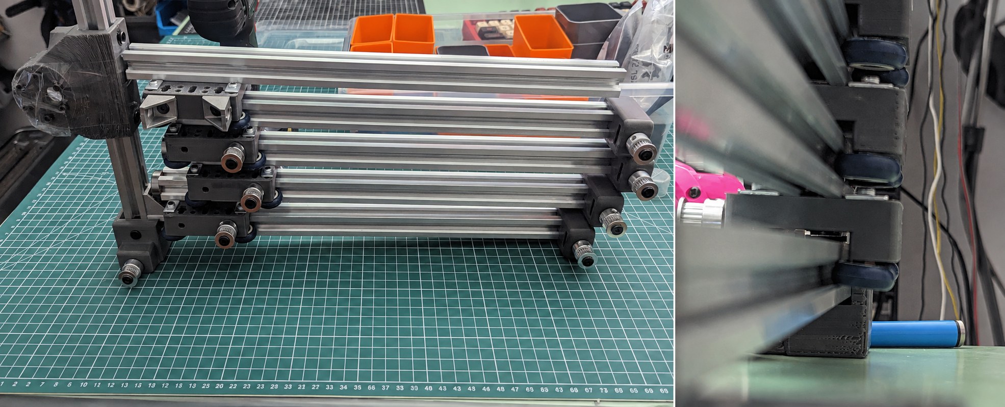
My first gantry design ran on rubberised wheels. Under loads of 250 g the rails deflected enough to lose pickup. Swapping to bearings fixed it but added mass to all rails — the worst place to put it on a crane.
I took the trade: a stiff arm can be lightened, a floppy one can't be stiffened. Recovered the weight margin by tightening the bearing-to-rail tolerance, redesigning the gantry carriages and machining slots in the rails.
Smooth operator
V1 & V2 consisted of a steel tube, a high mounted servo for an off-centre vertical pivot, and a horizontal pivot platform with weight distributed across 3 bearings. All printed parts were in PLA.
When I took over the design & fabrication:
All PLA printed parts were replaced with PETG.
Overall weight was reduced by replacing the steel tube with a single centrally mounted servo.
Horizontal pivot platform was fully redesigned with a 5 bearing base, distributed to account for the maximum torque points during operation.
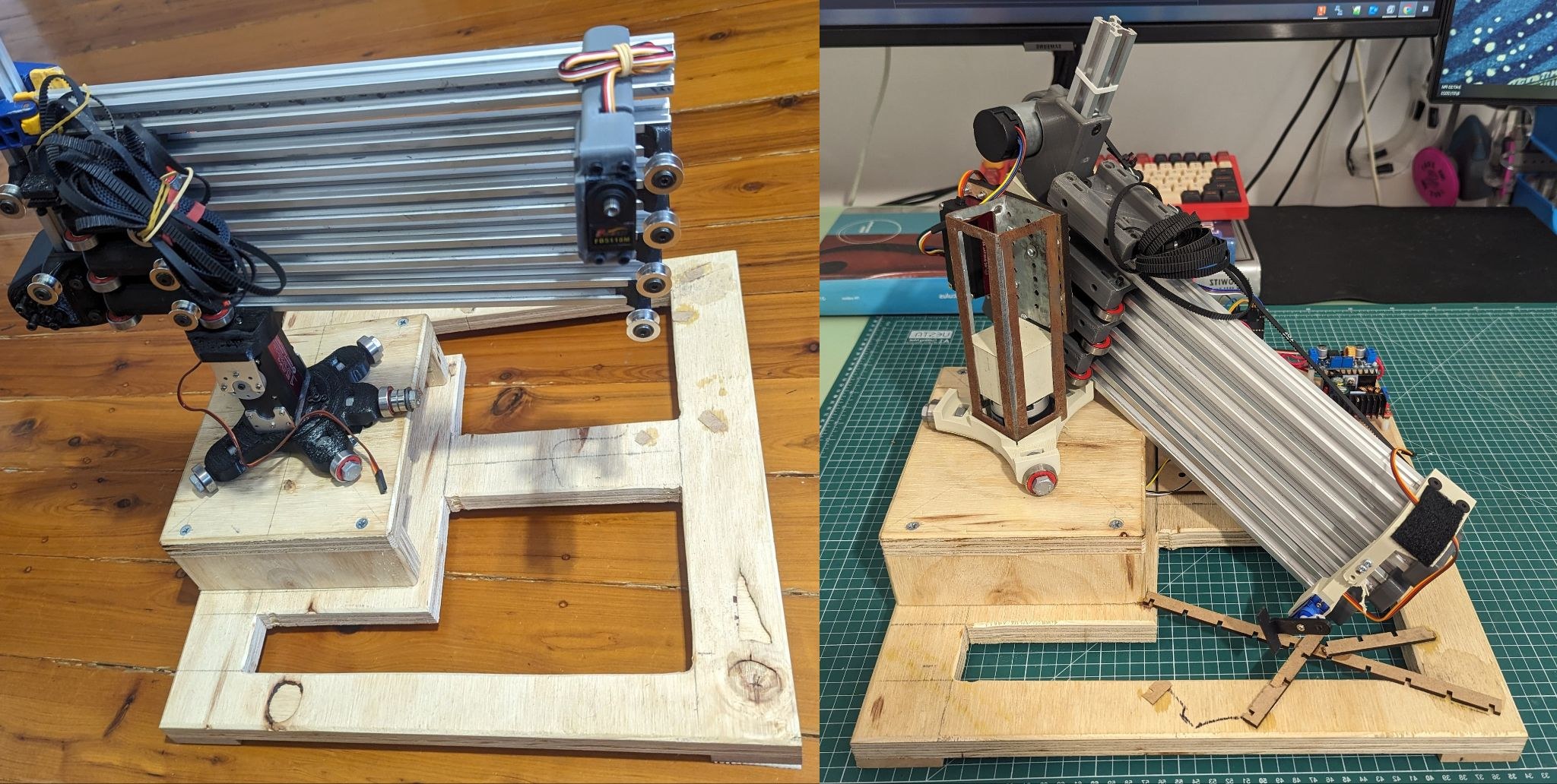
Warman device v3 vs. v2
What I'd change
The mass of subsystems was estimated once early on from the components expected to persist through prototyping — and every fix during testing forced added mass that that estimate never absorbed. I'd carry a live mass budget from the first prototype and update it at every design change, rather than treating the first number as settled.
Project management and inter-group communication could have been improved by assigning a dedicated manager to monitor accountability, capacity constraints, and project timelines.
Competition highlight
Loads YouTube when selected. Watch on YouTube